
Translating with Sprinky AI...
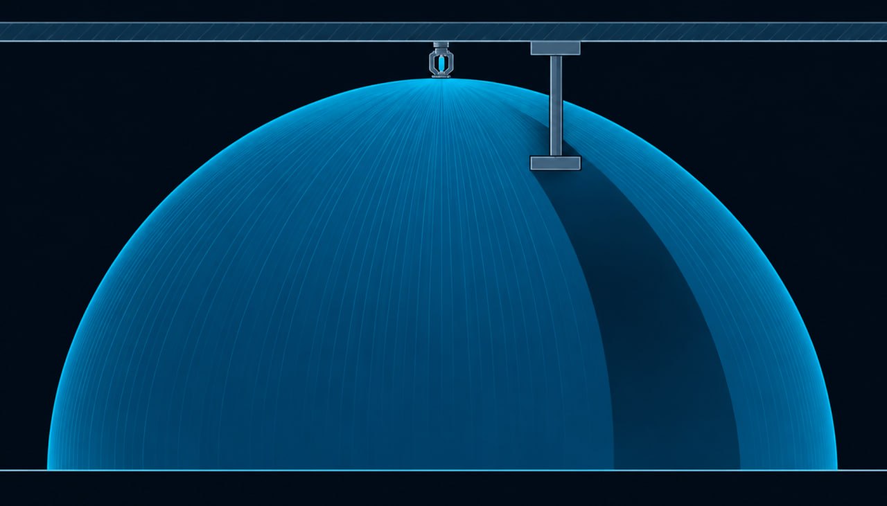
Sprinky AI Translation AssistantA sprinkler’s coverage boundary does not tell the whole story. Walls and partitions can block the discharge, leaving parts of the floor dry even when they sit within the sprinkler’s nominal coverage area. These dry spaces are known as shadow areas.
Checking shadow areas is an important part of sprinkler placement. A small change in location can reduce the obstructed area, bring a layout within the permitted limit and, in some cases, avoid additional sprinklers. The key is to understand how to draw the shadow area, which limit applies and how nearby obstructions affect the result.
Table of Contents
- Key Takeaways
- What Is a Shadow Area?
- How to Draw a Sprinkler Shadow Area
- The NFPA 13 Shadow Area Limit for Residential Sprinklers
- Shadow Areas for Standard Spray and Extended Coverage Sprinklers
- Using NSVCad to Evaluate Sprinkler Placement
- Check the Geometry Before Adding Sprinklers
Key Takeaways
- Draw shadow areas in plan view and account for every obstruction within the sprinkler’s coverage.
- NFPA 13 permits 15 ft² of cumulative shadow area per residential sprinkler.
- Equivalency-based shadow area values for other sprinkler types require approval from the authority having jurisdiction.
- Compare sprinkler locations and soffit geometry before deciding that additional sprinklers are necessary.
What Is a Shadow Area?
The shadow area concept was introduced in the 2013 editions of NFPA 13D and NFPA 13R. It describes floor areas that sprinkler discharge cannot reach because an obstruction, such as a wall or partition, blocks the water’s path.
When these dry areas become too large, sprinkler system effectiveness may be reduced. That is why identifying them is more than a drawing exercise: the geometry must be checked against the applicable requirements.
Two questions need to be answered separately:
- Where is the shadow area? Establish its boundaries from the sprinkler location and the surrounding obstructions.
- How much shadow area is permitted? Apply the requirement or approved design approach appropriate to the sprinkler type.
How to Draw a Sprinkler Shadow Area
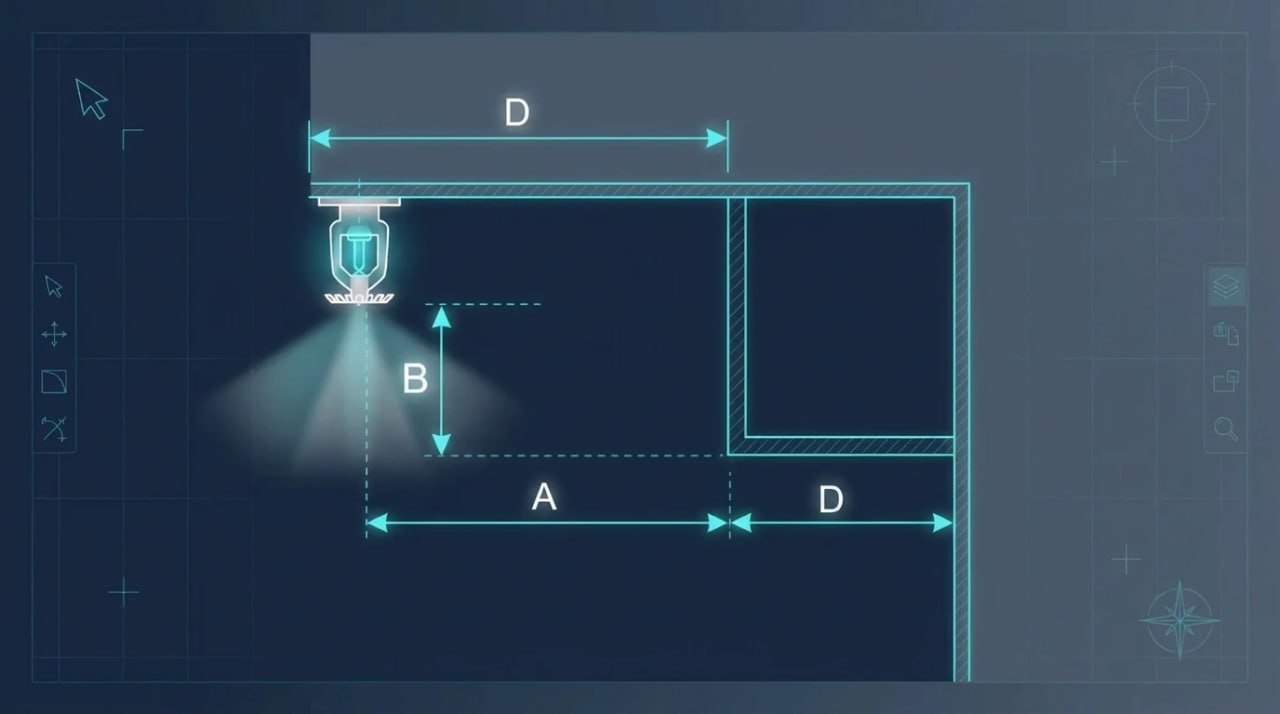
Identify the shadow area in plan view, using the centre of the sprinkler head as the starting point.
- Mark the sprinkler’s coverage boundary.
- Draw a line from the centre of the sprinkler to the far edge of the obstructing wall or partition.
- Extend that line beyond the obstruction until it meets the next obstruction within the sprinkler’s coverage.
- Identify the bounded floor space behind the obstruction. This is the shadow area.
- If the extended line reaches the coverage boundary first, stop the shadow area at that boundary.
- Repeat the process for every obstruction within the sprinkler’s coverage.
The coverage boundary matters. A projected shadow may continue geometrically beyond it, but the shadow area being assessed for that sprinkler is limited to the space within its coverage.
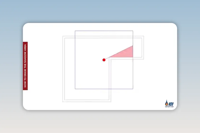
Where several walls or partitions create separate dry spaces, account for all of them. Checking only the largest shadow can miss a cumulative total that exceeds the permitted area.
The NFPA 13 Shadow Area Limit for Residential Sprinklers
Earlier editions recognised shadow areas caused by walls and partitions. The 2019 edition of NFPA 13 established a specific allowance of 15 ft² of cumulative dry area per residential sprinkler.
The important words are cumulative and residential. The allowance is not 15 ft² for each obstruction, and it is not a general limit that can automatically be applied to standard spray or extended coverage sprinklers.
For a residential sprinkler affected by several obstructions, calculate each individual shadow area and add the results:
Cumulative shadow area = shadow area 1 + shadow area 2 + shadow area 3 + any remaining shadow areas
Calculating the Area of a Trapezoid
In the illustrated residential layout, the dry spaces can be divided into trapezoids. Calculate each one using:
Trapezoid area = (base 1 + base 2) × height ÷ 2
The bases are the two parallel sides. The height is the perpendicular distance between them. With dimensions measured in feet, the resulting area is in square feet.
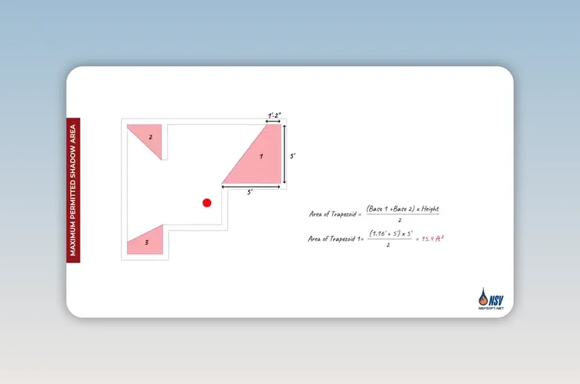
For project use, consult the applicable edition of NFPA 13. The residential allowance should not be treated as a substitute for the other coverage and obstruction requirements.
Shadow Areas for Standard Spray and Extended Coverage Sprinklers
The residential 15 ft² allowance raises a practical question: how should a designer assess shadow areas for other sprinkler types when NFPA 13 does not explicitly specify an equivalent numerical limit?
In 2012, Professor Kenneth Isman, former vice president of the National Fire Sprinkler Association, proposed an approach based on the equivalency principle. Rather than transferring the residential allowance to non-residential sprinklers, the method derives a reference shadow area from an obstruction arrangement already permitted by NFPA 13.
The Isman Method: Starting with a Permitted Obstruction
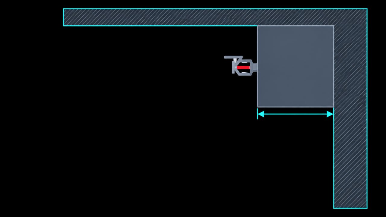
Consider a standard spray sprinkler in a light hazard occupancy, installed 3 ft from a column measuring 1 ft by 1 ft.
Applying the three times rule for standard spray sprinklers permits an arrangement with a dry area behind the column. Calculating that area trigonometrically gives approximately 13.5 ft².
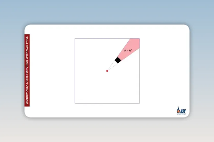
The same approach can be applied to ordinary and extra hazard occupancies. For extended coverage sprinklers, the analysis incorporates the four times rule instead of the three times rule. The resulting reference areas therefore depend on both the sprinkler type and the occupancy conditions.
These derived values are not explicit shadow area limits in NFPA 13. Their use in a sprinkler system design is subject to approval by the authority having jurisdiction, or AHJ. This distinction is essential: an equivalency-based proposal is not the same as a directly stated code allowance.
Using NSVCad to Evaluate Sprinkler Placement
Manual geometry explains the method, but testing several sprinkler positions means repeating the calculations. In NSVCad, the cumulative shadow area updates dynamically as the sprinkler moves, making it easier to compare locations.
The following example uses the bedroom and living room of Unit 102, with the 2025 edition of NFPA 13 selected as the design reference.
Bedroom: Repositioning a Residential Pendent Sprinkler
The bedroom has a suspended ceiling at 9.5 ft. We begin with a residential pendent sprinkler in a layout similar to the earlier trapezoid example.
As the sprinkler moves, the software calculates the combined shadow area and displays the result beside the sprinkler. The colour feedback makes the effect of each position clear:
- Blue coverage indicates that the cumulative shadow area remains within the 15 ft² limit.
- Red shadow regions identify a position where the cumulative area exceeds the threshold.
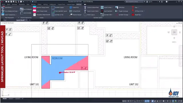
This is why sprinkler placement should be tested rather than assumed. Moving away from one obstruction may increase the shadow behind another. The useful position is one that brings the combined result within the limit, not simply one that improves a single corner.
Once a suitable bedroom location is established, we can move on to the living room.
Living Room: Comparing the North and South Soffits
The living room has no suspended ceiling, and its structural ceiling height is 10 ft. For this layout, we use sidewall sprinklers and compare installation on the north and south soffits.
The two positions produce very different results because the soffit dimensions affect both obstruction protection and the shadow area.
North Soffit: A Layout Requiring Three Sprinklers
When the north soffit is selected, the software flags that its width exceeds 8 inches. In this arrangement, a pendent sprinkler is required to protect the area beneath it.
The proposed sidewall sprinkler position also creates more than 15 ft² of shadow area. Taking both issues into account, the north soffit option would ultimately require three sprinklers to protect the room fully.
South Soffit: Protection with One Sidewall Sprinkler
The south soffit is 8 inches wide. In the demonstrated arrangement, the sidewall sprinkler can protect the area behind itself, eliminating the need for an additional pendent sprinkler beneath that soffit.
The north soffit is now in front of the sidewall sprinkler. Its width and depth are both within 24 inches, allowing the area beneath it to be protected in accordance with the NFPA 13 conditions used in this example.
The cumulative shadow area also remains within 15 ft². As a result, the living room can be protected with one sidewall sprinkler.
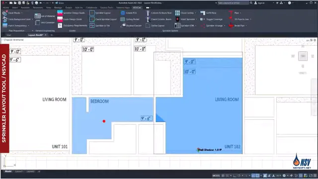
These dimensions should be read in the context of this particular arrangement, not as standalone rules for every soffit. The comparison shows why soffit geometry and shadow area need to be assessed together.
Check the Geometry Before Adding Sprinklers
A shadow area problem does not always mean another sprinkler is the first solution. Start by drawing the dry regions accurately, calculating their cumulative area and checking the requirement appropriate to the sprinkler type.
Then compare alternative locations. In the bedroom, repositioning brings the shadow area within the residential allowance. In the living room, choosing the opposite soffit changes the result from a three-sprinkler arrangement to protection with one sidewall sprinkler.
The aim is not simply to minimise the sprinkler count. It is to find a location that satisfies the applicable coverage, obstruction and shadow area requirements together.
Test Sprinkler Placement with NSVCad
Download a free trial to evaluate sprinkler coverage and calculate cumulative shadow areas as you adjust the layout.

No comments yet. Be the first to share your thoughts!