Introduction:
Predicting the precise coverage pattern of a fire sprinkler is challenging, as it depends on factors such as fire conditions, orifice size, deflector shape, and water discharge pressure.
At lower pressures, the coverage area often approximates a circle, while at higher pressures, it tends to become more elliptical.
However, NFPA 13 (2025 Edition, Section 9.5.2.1) requires that the coverage area be assumed as a rectangle.
This assumption increases flexibility in sprinkler placement by not requiring fixed spacing between sprinklers.
Nevertheless, determining the coverage area can be complicated in some cases.
The S × L method is the standard approach for determining a sprinkler’s coverage area.
Per NFPA 13, the protection area per sprinkler (As) is calculated as follows, assuming a rectangular (or square, if S = L) coverage area with the sprinkler at its center:
- Along branch lines as follows:
- Determine distance between sprinklers (or to wall or obstruction in the case of the end sprinkler on the branch line) upstream and downstream
- Choose the larger of either twice the distance to the wall or the distance to the next sprinkler
- Define dimension as ‘S’
- Between branch lines as follows:
- Determine perpendicular distance to the sprinkler on the adjacent branch line (or to a wall or obstruction in the case of the last branch line) on each side of the branch line on which the subject sprinkler is positioned
- Choose the larger of either twice the distance to the wall or obstruction or the distance to the next sprinkler
- Define dimension as ‘L’
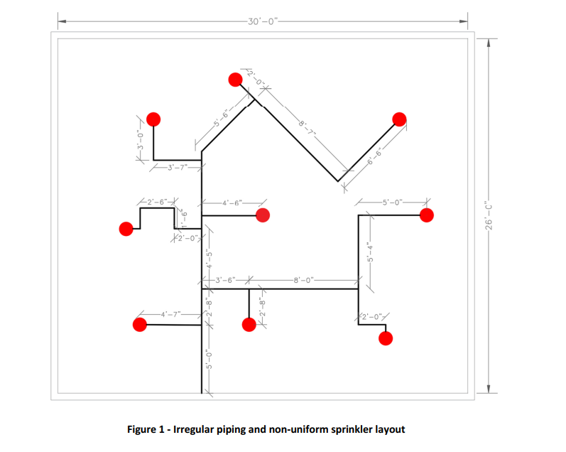
This method relies on piping routes, making it difficult to determine S and L when piping is irregularly shaped or sprinklers are arranged non-uniformly, as shown in Figure 1.
This article introduces a general method—the Sketch-Based Method—to determine sprinkler coverage areas more effectively in such scenarios.
Sketch-Based Method:
According to NFPA 13, a sprinkler’s coverage area is determined by the placement of adjacent sprinklers or walls.
Each sprinkler protects the space between itself and neighboring sprinklers (or walls), effectively covering half the floor area between them, with the adjacent sprinkler covering the other half.
The coverage area must be a rectangle or square, with the sprinkler positioned at its center.
Unlike the S × L method, the Sketch-Based Method disregards pipe routes, as the direction of piping does not influence the sprinkler’s coverage area.
The following examples illustrate the application of this method.
Example 1: Uniformly Spaced Sprinklers
Determine the coverage area of the blue sprinkler in Figure 2 .
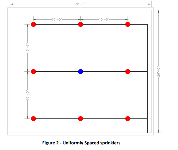
Solution) This example features uniformly spaced sprinklers. According to NFPA 13 requirements, S and L are both 10 ft, resulting in a coverage area of 100 ft².
To apply the Sketch-Based Method, we determine the coverage area of the blue sprinkler step by step.
For clarity, adjacent sprinklers are colored black in each step, as shown in the following figures.
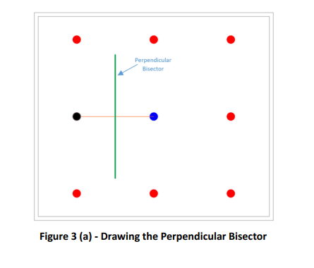
Begin with the sprinkler to the left. Draw a line between the centers of the blue and black sprinklers (orange line) and its perpendicular bisector (green line).
The blue sprinkler covers the right side of the green line, while the black sprinkler covers the left side.
[Figure 3(a)]
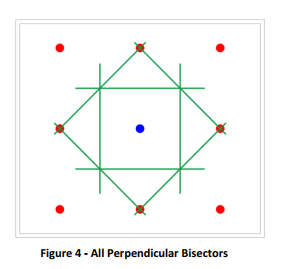
Repeat this process for all adjacent sprinklers, as illustrated in Figures 3(b) through 3(h).
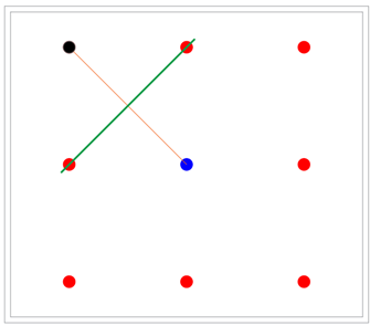
Figure 3 (b)
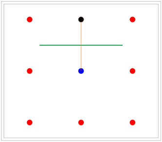
Figure 3 (c)
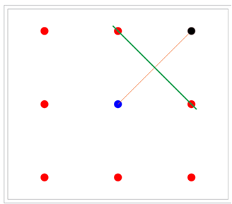
Figure 3 (d)
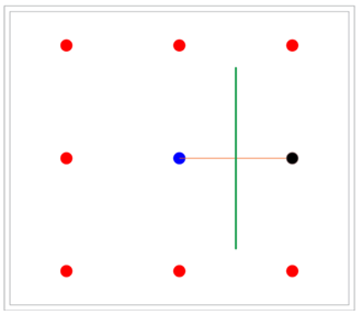
Figure 3 (e)
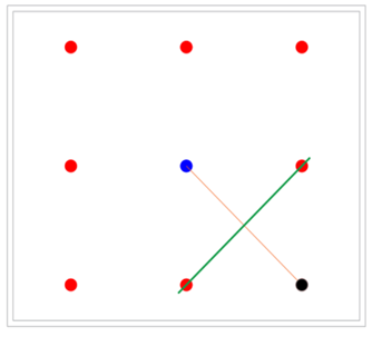
Figure 3 (f)
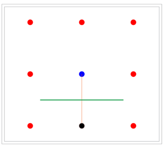
Figure 3 (g)
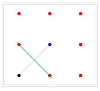
Figure 3 (h)
The blue sprinkler protects the area bounded by the green lines, shown with a blue hatch in Figure 5.
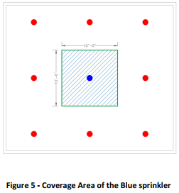
As shown, the area is a square with the sprinkler at its center, measuring 10 ft by 10 ft. Thus, the coverage area is 100 ft², meeting NFPA 13 requirements for a rectangular shape with the sprinkler centered.
Example 2: Slightly Non-Uniform Sprinkler Arrangement
Determine the coverage area of the blue sprinkler in Figure 6.
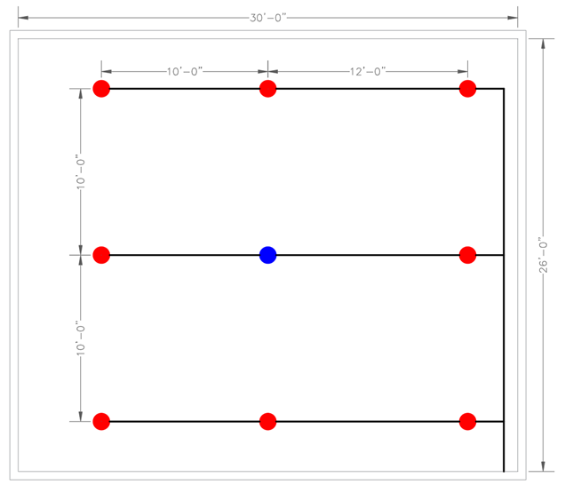
Figure 6 - Sprinkler Arrangement
Solution) In this example, the S × L method requires comparing the distances between the blue sprinkler and the left and right sprinklers, selecting the larger value.
Here, S is 12 ft, and L is 10 ft, yielding a coverage area of 120 ft².
Using the Sketch-Based Method, draw the perpendicular bisectors for all adjacent sprinklers, as shown in Figure 7.
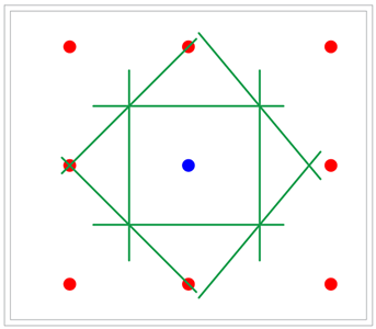
Figure 7 - All Perpendicular Bisectors
The initial coverage area, shown with a red hatch in Figure 8, is rectangular but does not have the sprinkler at its center, which does not meet NFPA 13’s centering requirement.
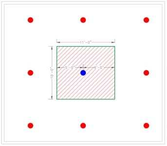
Figure 8 - Initial Coverage Area (Sprinkler Not Centered)
In such cases, determine the bounding box—the smallest rectangle that completely encloses the initial coverage area—as shown in Figure 9.
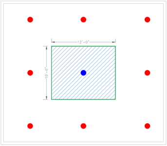
Figure 9 - Coverage Area of the Blue sprinkler
The bounding box measures 12 ft by 10 ft, resulting in a coverage area of 120 ft², consistent with the S × L method.
Example 3: Non-Uniformly Spaced Sprinklers
Determine the coverage area of the blue sprinkler in Figure 10.
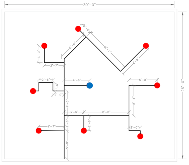
Figure 10 – Non-Uniformly Spaced Sprinklers
Solution) In this case, the non-uniform sprinkler arrangement makes it challenging to determine S and L using NFPA 13’s method.
The Sketch-Based Method offers a more practical approach.
Draw the perpendicular bisectors for all adjacent sprinklers, as shown in Figure 11.
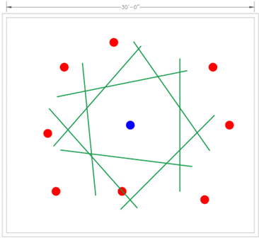
Figure 11 - All Perpendicular Bisectors
The initial coverage area, shown in Figure 12, is irregular and not rectangular, failing to meet NFPA 13’s shape requirement.
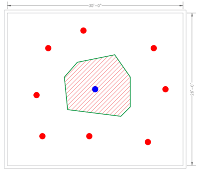
Figure 12 - Initial coverage area with the irregular shape
Next, determine the bounding box.
Manually calculating the bounding box of an irregular shape can be complex, requiring precise measurements and geometric understanding.
Without computer algorithms, manual estimation may introduce errors, impacting accuracy.
Several rectangles that entirely enclose the initial coverage area are shown in Figures 13(a) through 13(c).
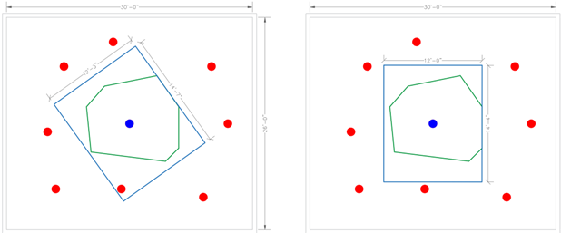
Figure 13 (a) and 13 (b)
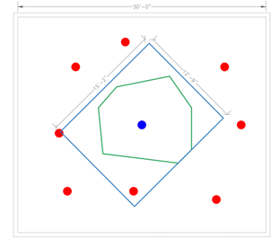
Figure 13 (c)
The bounding box (the smallest rectangle) is shown in Figure 14.
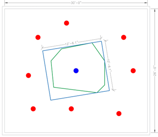
Figure 14 - Coverage Area of the Blue sprinkler
The bounding box measures 12.51 ft by 10.51 ft, resulting in a coverage area of 131.48 ft².
Find ACA App:
The Find ACA within NSVCad software is a tool for finding sprinklers' coverage areas in seconds. After running the app, the form will pop up, and the user will select the Unit, Type of sprinkler, and coverage area based on the NFPA requirements.
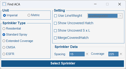
Figure 15 - App`s form
In AutoCAD, the software calculates the “S,” “L,” and the sprinklers' coverage area by defining the room boundaries and selecting one of the sprinkler blocks.
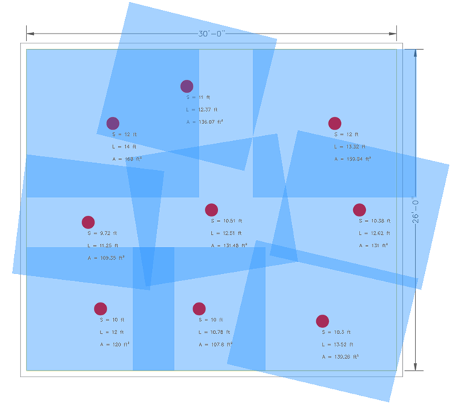
Figure 16 - The ‘S’, ‘L’ and Coverage area of sprinklers
You can watch the video of this tool on the NSVsoft website (nsvsoft.net) or the NSVCad channel on YouTube.
Conclusion
The Sketch-Based Method provides a practical alternative to the NFPA 13 “S × L” method for determining sprinkler coverage areas, particularly in non-uniform layouts where piping routes are irregular. By drawing perpendicular bisectors between a sprinkler and its neighbors, this method defines an initial coverage area, which is then enclosed within a bounding box to meet NFPA 13’s requirement of a rectangular shape with the sprinkler at its center. While effective, the method’s reliance on manual bounding box calculations for irregular shapes can introduce challenges, suggesting potential benefits from computational tools to enhance accuracy. This approach offers fire protection designers greater flexibility in addressing complex sprinkler arrangements, ensuring compliance with NFPA 13 standards.


No comments yet. Be the first to share your thoughts!