
Translating with Sprinky AI...
Sprinky AI Translation AssistantA uniform sprinkler layout starts with two questions: how many sprinklers does the room need, and how should we distribute them? The first is an area calculation. The second requires us to consider spacing, wall offsets, and room proportions together.
NFPA 13 defines coverage and spacing requirements for different sprinkler types. Designers can then use different calculation methods to develop a practical arrangement within those limits. Here, we will work through four approaches for upright and pendent sprinklers, using the same rectangular room throughout, before applying the process with the Sprinkler Arrange tool in NSVCad.
The calculations below develop a uniform layout, not a complete sprinkler system design. The numerical limits belong to the stated NFPA 13 example and should not be treated as universal values for every sprinkler, occupancy, or project.
What You'll Learn
- Divide room area by permitted sprinkler coverage and round upwards to establish an area-based minimum.
- Changing the starting direction can change the total sprinkler count in a uniform grid.
- Proportional layouts use room dimensions to guide sprinkler counts before whole-number rounding.
- Every arrangement requires coverage, spacing, and wall-distance checks, including layouts generated by software.
Table of Contents
- Start with the Coverage and Spacing Requirements
- Calculate the Minimum Number of Sprinklers
- Method 1: Begin with Maximum Spacing Along the Length
- Method 2: Begin with Maximum Spacing Across the Width
- Method 3: Derive the Width Count from the Length Count
- Method 4: Derive the Length Count from the Width Count
- Transfer the Calculations to the Layout
- Compare the Options and Check the Limits
- Automate the Comparison with NSVCad’s Sprinkler Arrange Tool
- A Consistent Process for Uniform Sprinkler Placement
Start with the Coverage and Spacing Requirements
The 2025 edition of NFPA 13 addresses different sprinkler types in Chapters 10 through 14. Before calculating a grid, establish the coverage and spacing limits that apply to the selected sprinkler and project conditions.
For our example, we will use:
- Room dimensions: 100 ft long by 70 ft wide.
- Ceiling: Flat and horizontal.
- Occupancy classification: Ordinary hazard.
- Sprinkler type: Standard spray upright or pendent.
- Maximum coverage area used: 130 ft² per sprinkler.
- Maximum spacing used: 15 ft.
Coverage area and spacing are separate checks. A layout must keep the area assigned to each sprinkler within the applicable limit while also keeping the distance between sprinklers within the permitted range.
Calculate the Minimum Number of Sprinklers
First, calculate the room area:
Then divide the room area by the maximum coverage area per sprinkler:
Always round a fractional sprinkler count upwards. Partial sprinklers are not an option in fire protection design.
The result gives us an area-based minimum of 54 sprinklers. It does not yet tell us how many heads to place in each direction. A regular grid may need more than 54 because the number along both the length and width must be a whole number, and the resulting spacing must satisfy the applicable requirements.
Method 1: Begin with Maximum Spacing Along the Length
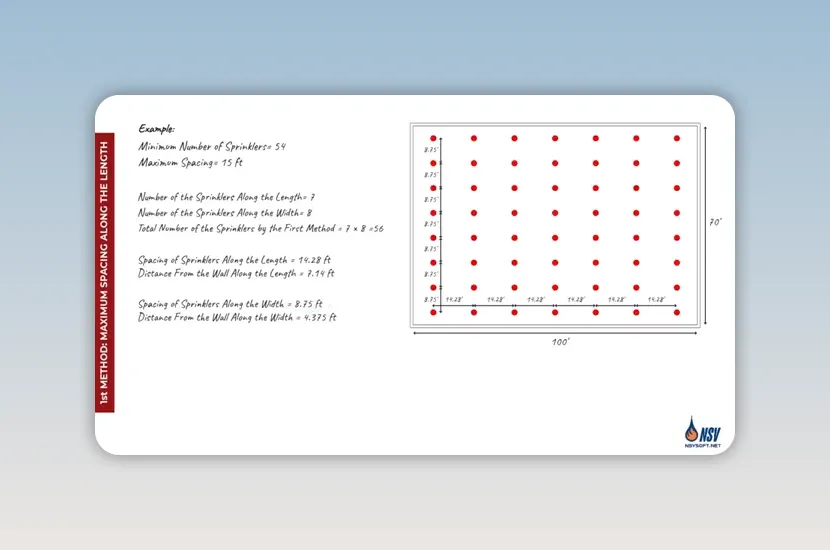
The first approach uses the maximum permitted spacing to establish the number of sprinklers along the 100 ft length. We then use the area-based minimum to determine the number across the width.
Step 1: Find the Number Along the Length
Divide the room length by the maximum spacing and round upwards:
Step 2: Find the Number Across the Width
Divide the area-based minimum by the number along the length:
The resulting grid contains 7 × 8 = 56 sprinklers, which is two more than the area-based minimum.
Step 3: Calculate Uniform Spacing and Wall Offsets
Divide each room dimension by its corresponding sprinkler count:
- Spacing along the length: 100 ÷ 7 ≈ 14.29 ft.
- Spacing across the width: 70 ÷ 8 = 8.75 ft.
- End-wall offset along the length: Half the lengthwise spacing, approximately 7.14 ft.
- Side-wall offset across the width: Half the widthwise spacing, 4.375 ft.
Using half-spacing at both ends centres the grid in the room. There are six full intervals between seven sprinklers along the length, plus a half-interval at each wall. Together, those intervals fill the 100 ft dimension.
For this uniform grid, the coverage rectangle per sprinkler is approximately 14.2857 × 8.75 = 125 ft², below the example’s 130 ft² limit. Both directional spacings are also below 15 ft.
Method 2: Begin with Maximum Spacing Across the Width
The second method reverses the starting direction. Instead of calculating the lengthwise count first, we begin with the 70 ft width.
- Calculate the count across the width: 70 ÷ 15 = 4.67, rounded up to 5.
- Calculate the count along the length: 54 ÷ 5 = 10.8, rounded up to 11.
- Calculate the total: 11 × 5 = 55 sprinklers.
The spacing and offsets become:
- Spacing along the length: 100 ÷ 11 ≈ 9.09 ft.
- Spacing across the width: 70 ÷ 5 = 14 ft.
- End-wall offset along the length: Approximately 4.55 ft.
- Side-wall offset across the width: 7 ft.
The coverage rectangle is approximately 127.27 ft² per sprinkler, and both directional spacings remain below 15 ft.
Simply changing the starting direction reduces this arrangement from 56 to 55 sprinklers. That is a useful reason to test both directions rather than assuming the first grid is the most efficient.
Method 3: Derive the Width Count from the Length Count
The third method uses the room’s proportions as the starting point. If a room is twice as long as it is wide, we aim initially for twice as many sprinklers along the length as across the width.
For our 100 ft by 70 ft room, the width is 0.7 times the length. Define:
- L: Number of sprinklers along the length.
- W: Number of sprinklers across the width.
The proportional relationship is W = 0.7L, and the target sprinkler count is L × W = 54.
Solve for the Lengthwise Count
Substitute 0.7L for W:
Round upwards to 9 sprinklers along the length. Then calculate the widthwise count from the required total:
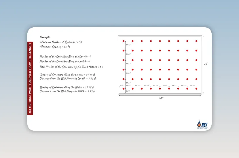
The final grid contains 9 × 6 = 54 sprinklers, matching the area-based minimum.
Calculate the Spacing and Offsets
- Spacing along the length: 100 ÷ 9 ≈ 11.11 ft.
- Spacing across the width: 70 ÷ 6 ≈ 11.67 ft.
- End-wall offset along the length: Approximately 5.56 ft.
- Side-wall offset across the width: Approximately 5.83 ft.
The resulting coverage rectangle is approximately 129.63 ft² per sprinkler. Both directional spacings are below 15 ft.
This method produces the lowest sprinkler count among the four arrangements for these particular dimensions. It also creates more similar spacing in the two directions. The room proportions guide the initial calculation, but whole-number counts mean the final grid does not preserve the ratio exactly.
Method 4: Derive the Length Count from the Width Count
The fourth method uses the same proportional idea but solves for the widthwise count first.
The room length is approximately 1.43 times its width, so:
Substitute this relationship into L × W = 54:
Round upwards to 7 sprinklers across the width. Then calculate the lengthwise count:
The final arrangement contains 8 × 7 = 56 sprinklers, with:
- Spacing along the length: 100 ÷ 8 = 12.5 ft.
- Spacing across the width: 70 ÷ 7 = 10 ft.
- End-wall offset along the length: 6.25 ft.
- Side-wall offset across the width: 5 ft.
The coverage rectangle is 125 ft² per sprinkler, with both spacings below 15 ft.
Although Methods 3 and 4 begin with the same room proportions, they produce different results because we round the first calculated count upwards before determining the second. The order of calculation matters.
Transfer the Calculations to the Layout
Once the counts, spacing, and wall offsets are known, the placement procedure is the same for all four methods:
- Choose one corner of the room as the starting reference.
- Draw a line parallel to one wall at the calculated half-spacing offset.
- Draw a second line parallel to the adjoining wall at its corresponding half-spacing offset.
- Place the first sprinkler at the intersection.
- Copy the sprinkler along the length at the calculated lengthwise spacing.
- Repeat the row across the width at the calculated widthwise spacing.
This produces a centred rectangular grid with consistent spacing and equal offsets at opposite walls. Retain calculation precision when constructing the grid so that rounded display values do not accumulate into a placement error.
Compare the Options and Check the Limits
For the same room and the same design inputs, our four methods produce:
| Method | Grid (L × W) | Total Sprinklers |
|---|---|---|
| Length-first maximum spacing | 7 × 8 | 56 |
| Width-first maximum spacing | 11 × 5 | 55 |
| Width derived from length | 9 × 6 | 54 |
| Length derived from width | 8 × 7 | 56 |
These are practical calculation techniques, not separate NFPA requirements. No one method will always give the lowest count for every room.
Do not stop at the total number of sprinklers. Check the resulting coverage area, maximum spacing, minimum spacing, and wall distances against the applicable requirements.
Minimum sprinkler separation matters because sprinklers placed too close together can create cold soldering, where discharge from an operating sprinkler cools a nearby sprinkler and can delay its operation. Minimum wall distances also need attention to avoid placing sprinklers in dead-air spaces.
The half-spacing offsets used here centre the grid. They are calculated layout offsets, not a statement of the minimum permitted wall clearance.
Automate the Comparison with NSVCad’s Sprinkler Arrange Tool
Manual calculations make the layout logic clear. Software can then help us generate and compare arrangements without repeating the same arithmetic for every room.
In NSVCad, the Sprinkler Arrange workflow is:
- Open the tool. Choose the sprinkler type and set the spacing and coverage inputs to match the project specifications.
- Define the room. Select two corner points of the rectangular space.
- Compare the options. Review the proposed sprinkler counts and spacings, with options presented from lower to higher counts.
- Select an arrangement. The tool places the sprinklers automatically within the room.
- Continue to other rooms. If the sprinkler type and hazard classification remain unchanged, select the next room and choose a preferred layout option.
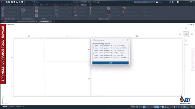
The value of automation is the ability to compare alternatives quickly. The underlying design checks remain essential: establish the correct inputs, review the proposed spacing and offsets, and confirm that the selected arrangement suits the project.
Try NSVCad’s Sprinkler Arrange Tool
Download the free trial to compare uniform sprinkler layout options and place your selected arrangement automatically.
A Consistent Process for Uniform Sprinkler Placement
Begin with the area-based minimum, calculate whole-number counts in both directions, and use those counts to establish spacing and wall offsets. Comparing length-first, width-first, and proportional approaches can reveal a more efficient grid than the first arrangement you calculate.
In this example, the nine-by-six layout reaches 54 sprinklers, while the alternatives require 55 or 56. The practical lesson is to compare arrangements and verify their limits, rather than treating one calculation sequence as the answer for every room.



No comments yet. Be the first to share your thoughts!