Basic Troubleshooting Tips for Fiber Optic Communication Utilized in Fire Alarm Networks.
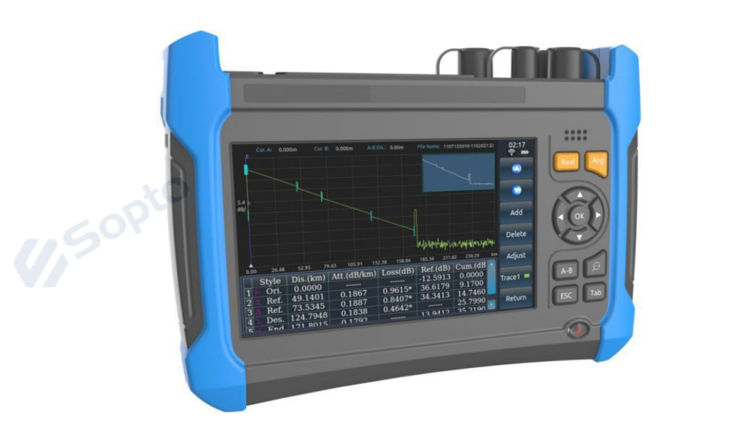
Generally, the fire alarm technician does not have access to sophisticated electronic equipment required to troubleshoot fiber optic systems such as an optical time-domain reflectometer (ODTR),
power meters and other sophisticated optical diagnosing equipment.
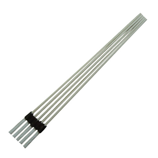
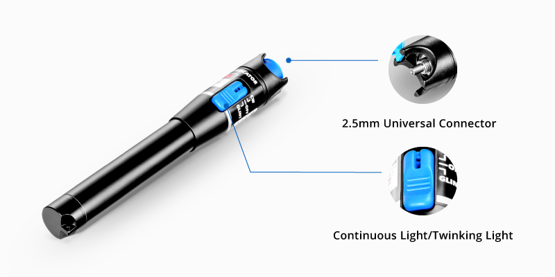
Two relatively cheap tools the fire alarm technician can utilize are a fiber optic light and a fiber optic cleaning stick.
Visual fault indicating lights are available on Amazon for about $30.
Cleaning sticks run about the same price, but you’ll need to know what kind of connection your system utilizes.
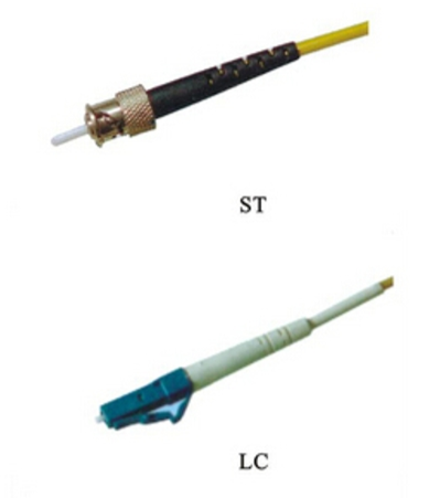
Most connections I see are either ST or LC connectors.
The most common problems I run across are either dirty connectors or broken fiber strands.
Retaining fiber connection covers in a small zip lock bag in the panel and cleaning any connectors that must be disassembled are a good start to preventing problems.
However, fiber strands are brittle and cannot be bent past acertain radius or they break.
I have found installing a WIC box or other bulkhead near the panel and utilizing a jumper to interconnect between the bulkhead and the panel saves a lot of heartache.
If a jumper is damaged it is easy to install a new one and return the fiberlink to working order.
On the other hand,
if you break a strand on the main fiber optic line,
you usually require a communication technician to come in and repair the fiber by fusion splicing a new connector on or you have to re-pull the fiber.
Thus the addition of a WIC box usually means you are money ahead in the long run.

With the advent of inter-panel Ethernet communication,
fiber will probably be installed less and less.
However, if fiber is the only existing infrastructure it still may be chosen over other modes of network communication.
It is an extremely good idea to build a network map if you don’t have one available for your site.
You want to have this map available before you have network communication issues.
If possible label all fiber connections and try and keep your map updated if there are any changes to the network.
Network faults can cause serious communication issues, data collisions, etc.
It is important to fix these communication faults as soon as possible after their occurrence.
Usually a degraded fiber connection will generate a trouble on the fire alarm panel.
You need to know whether you’re communicating utilizing a ring or loop (Style 7) or does it have a head and tail end (Style 4)?
If you are running a Style 4 network it is helpful to know which panels serve as your head and tail ends.
In systems that have a graphical interface sometimes they will show you where the network fault is at.
Unfortunately, that is not always the case. You can usually narrow the problem down by looking at your network interface cards.
You should have transmit and receive lights lighting periodically on both sides of the network interface card, both left and right.
Transmit (Tx) lights are usually green and receive (Rx) lights are usually red.
This should help you narrow down where the network break is. If you know the specification of your signal you can measure it with an inexpensive power meter.
Most fiber modems both send and receive data.
Ours transmit on 1310 nm and receive on 1550 nm.
Although, one port will primarily receive incoming data from its neighbor panel in the network and the other side will generally transmit to the next panel in the network;
you should still see both the Tx and Rx light up on each side of the NIC connection periodically.
We run left in (receive) right out (transmit).
If I only see Rx light up on a RH card or Tx on a LH card, I am going to assume I have a problem on the fiber that is connected to that port.
A lot of times communication technicians point towards your equipment as the cause of the problem.
A good way to test this without replacing a bunch of panel components is to roll the fiber from the left hand side to the right hand side or vice versa and see if your problem moves.
In other words if all the panel components are functioning properly and you roll the fiber your communication problem should move either at the panel you’re in or in a neighboring panel.
Once you’ve narrowed down that it is a fiber problem the first step is to shine light where you think the problem is at each junction point.
You want to look out for noticeably weak light on one strand versus another.
You also want to look for excessive light bleeding out of the fiber at the end connectors as this is a sign that they’re dirty or have failed. The first step is to clean them and see if this fixes the problem.
If you have found a problem that cannot be fixed by cleaning and you can replace this part with a factory jumper you would want to do that at this point.
The only other option is to pull new fiber with factory connections already installed.
If none of these steps solve your problem, call your communication professional.
To see more content, please click here nsvsoft.net/blog/
Josh Blake
Mr. Blake manages an unamed 33 panel network fire alrm system.


